


Read more
can bus properties and troubleshooting
good day everybody. My name is Abdulfatah Abdulrasheed
with Enovation Controls Technical Services. Today we are going to be speaking approximately the bodily
and electric traits of a CAN facts bus. We can also be reviewing some
troubleshooting strategies for the maximum, not unusualplace issues you're
possibly to come upon withinside the field. Before we begin, we ought to in all likelihood have a
quick dialogue on what a CAN facts bus is. CAN stands for controller vicinity community and it is
essentially a cord high-velocity facts bus that permits a couple of gadgets to talk with every
other. This is a multi-grasp facts bus. What that way is that any tool related to the community
can take manipulate the bus and transmit facts. To assist display a number of the
standards we are going to study today, we've got this panel at the back of us that has
all of the essential additives that you may locate in your ordinary CAN facts bus.
Let's zoom in to get a more in-depth view.
This panel is a bodily illustration of
what you may generally see on a CAN facts bus. We have a major bus, sometimes
called a spine, after which alongside the spine we
have distinctive gadgets stubbed out. We have an ECOM controller that we are going to use to transmit facts and display all
the gadgets which might be at the bus. We have stubbed out on stub range
an XMD valve controller. And then, on stub range
three, we've got a PV380 display. On some distance ends of the facts bus, we've got a
termination resistor placed all of the manners on the left and all of the manners at the right. A CAN bus
must be terminated at the same distance ends of the bus. So, we have got laid it out to offer you a bodily
illustration of what that ought to appear like. The CAN community makes use of bus topology. What
this means is you've got got a major harness or spine after which every tool is stubbed
out or daisy chained as you move alongside.
In this case, we are the usage of yellow
and inexperienced twisted pair cord. This is the minimal requirement for a CAN facts
bus. You also can use twisted shielded pair that is extra premier however it is a
little bit extra tough to manage. You can use quite a great deal of any wiring technique
at the CAN facts bus in this case we are the usage of a terminal strip to break up off to the
ECOM manipulation after which for the opposite stubs we are the usage of the Deutsch triangular
connector gadget together with a splitter. For the termination resistors, we are additionally the usage of
Deutsch termination plugs that have a built-in 120-ohm resistor it really is encapsulated in
epoxy to maintain it best and watertight. That quite a great deal covers all of the
bodily components of a CAN facts bus. Now let's speak about approximately a number of
the electric traits. The sign wires are referred
to as CAN Low and CAN Hi. The voltage that you may measure
on those wires goes to be
2. five volts, while no facts are being broadcast, after which CAN Low, will transfer
among 2. five and 1. five volts and CAN Hi will transfer among 2. five
and 3. five while it is broadcasting facts. Let's test the oscilloscope to
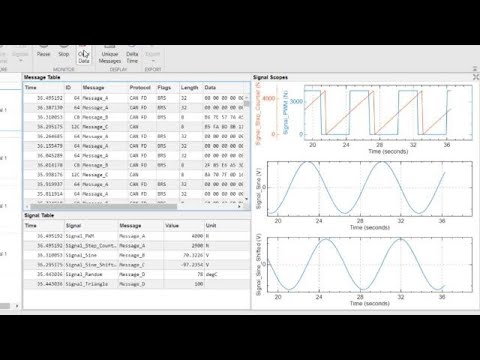
get a higher view of what this appears like. I even have the oscilloscope related to CAN Hi
on channel 1 and CAN Low on channel 2 and at the panel, I even have the XMD and the PV380
and the ECOM cable all broadcasting facts. What we are seeing now at the oscilloscope are the facts packets being broadcast
at diverse time intervals. I even have the oscilloscope installation for 1
volt consistent with the department so that you can see that the baseline for CAN facts is sitting at
approximately 2. five volts for CAN Hi and CAN Low. Let me separate the 2 indicators so that you
can see what I'm speaking approximately here. I'm going to elevate channel 1 up a bit bit.
Now I'll deliver it go into the reverse so it is at the
equal voltage reference as channel range 2 and as you could see withinside the time in among the
packets the voltage is sitting at 2. five volts. Now let's take a more in-depth study of the real facts
packet. I'm going to alternate our horizontal scale, and that is quite a great deal of what the message
appears like. I'm going to freeze-frame this now so that you can get a higher view.
As you could see while facts are lively CAN Hi is going among 2. five and 3. five volts and
CAN Low is going between 2. five and 1. five volts. If you study the common voltage or the mean
voltage that the oscilloscope is measuring, we've got approximately 2. nine volts on CAN
Hi and 2.14 volts on CAN Low. This is quite clean to look at what is going on
if you have an oscilloscope related, however extra than possibly all you've got is a multimeter. What does the voltage appear like
if you have a multimeter? As you could see, the maximum time the
voltage is at 2. five volts DC with periodic
Transition on CAN Hi to 3. five volts
and on CAN Low right all the way down to 1. five volts. When you are measuring this with a multimeter,
it will common those voltages together. So, you will get something simply more or less a little bit above 2. five on CAN Hi and
a touch bit beneath 2. five on CAN Low. So proper now, the common voltage
is ready at 2. fifty-six on CAN Hi after which we're going to transfer over to CAN Low and
the common there may be approximately 2. five. Now usually whilst you're measuring
those voltages with a multimeter CAN Hi goes to be
extremely extra than CAN Low. How a whole lot of a distinction you will
see relies upon at the bus loading. Right now, we are now no longer sending numerous records
at the bus so there is now no longer an entire lot of distinction among CAN High and CAN Low due to the fact
maximum of the time it is sitting there at 2. five volts. Let's test what occurs whilst you
Disconnect the whole lot from the
community besides for one tool. I'm going to unplug the ECOM cable and
the XMD and let's examine what occurs. Well, as you may see, there is a flood of records
in the community now. That's due to the fact the CAN controller withinside the PV380 is making an attempt to synchronize
with some other tool and there is not anything there. We can use this to our benefit due to the fact
the voltage you will degree with the multimeter now goes to be a whole lot
better on CAN Hi and plenty decrease on CAN Low. Let's test what the
voltage looks as if on CAN Hi and what we've got now's 2. nine volts and
then on CAN Low we've got 2.1 volts. It's a whole lot less difficult to decide what the common
voltage is at the records bus whilst you've got simply one tool linked. This will become
essential whilst we get into troubleshooting. The subsequent factor we want to speak approximately
is termination resistors. We've already referred to that at every cease of the bus
you need to have a one hundred twenty-ohm termination
Resistor as we've got positioned right here and right here.
Well, let's communicate approximately why this is so. The CAN bus is a high-velocity records bus and as
a sign propagates down the road if it is now no longer terminated a part of that sign will replicate
returned after which intervene with the following records sign coming down the road, and what that would do is
disrupt communications and the bus ought to fail. So, you can ask, "nicely what approximately
the stubs? The stubs do not have a termination resistor what
approximately reflections are there?" Well, the identical factor holds genuine for the stubs.
A sure quantity of signs will replicate returned, however, in case you preserve the stubs quick
sufficient then that might not motive trouble. If you've got got a definitely lengthy stub
relative to the period of your CAN bus, then that would pose trouble. The popular rule of thumb is to preserve
the stub period as quick as possible. I'm going to hyperlink an application
article from Texas Instruments that
Discusses the subject of termination
resistors and sign reflections. For the functions of this communique, the guideline of thumb is the CAN records bus has
to be terminated on each end. Now, let's test what
that resistance could appear like. I've become the energy off and I actually have a multimeter set to degree resistance and I
have it linked to the PV380. You could make your connection
to any location alongside this bus, and also you need to degree the identical resistance. So, what we display right here is ready 60 ohms which are
the parallel mixture of one hundred twenty-ohm resistors. This leads us into the following part of our
communique that is troubleshooting. The first step in troubleshooting a CAN records
bus is measuring the termination resistor so that you need to choose the maximum
handy spot to plug into
The CAN bus and the degree among CAN Hi
and CAN Low also you need to see 60 ohms. If the termination resistor is lacking you will most effective degree one hundred twenty ohms. I'll unplug one of
those terminators to illustrate that. As you may see the resistance
is now near one hundred twenty ohms. If you had 3 termination
resistors withinside the community it will be the parallel mixture of
3 resistors which could be forty ohms. That's now no longer as horrific however it is also now no longer as desirable
so you'd need to accurate that situation. So, in case you're most effective seeing one hundred twenty ohms
now, you will figure out in which at the records bus are we
lacking the termination resistor. A bodily inspection is usually
the nice manner to do that, however, if the harness is definitely complex and difficult
to get to if you may faucet into the harness midway someplace then you may inform on which facet of
the harness is lacking the termination resistor.
I'll exhibit that right here with the aid of using unplugging
one of the connectors at the spine. Now what we are measuring is ready
27 kilohms at the multimeter. We're measuring this 1/2 of the
spine and it looks as if there is no termination resistor installed, so we understand
the trouble is in this 1/2 of the harness. If I circulate my leads over to degree the resistance
in this 1/2 of the harness, as you may see we have more or less one hundred twenty ohms, so we understand that this
1/2 of the harness is well terminated. So, you'll need to locate the ways cease of this 1/2 of
the harness and upload a termination resistor. One factor to preserve in thought is that some
devices, like our Murphy PowerView colour displays, have an integrated termination
resistor this is a software program selectable. So, if this is the case, you are now no longer going
to peer that resistance whilst you degree it at the bus as it most effective becomes
engaged as soon as the show is powered up. In that example you will need to study the
records sheet for the tool this is linked to.
The subsequent maximum, not unusualplace trouble you will
come across is trouble withinside the harness itself in which someone has wired
CAN Hi and CAN Low backwards. Let's move in advance and change CAN Hi and CAN Low
on
our XMD valve controller and notice what we get. Typically, the place to begin goes to be to
degree your voltages someplace at the harness. Right now, you may see that CAN
Hi is measuring 2. four after which CAN Low is measuring 2.6. Now that is
contrary to what it ought to be. CAN Hi ought to usually be better than CAN Low. You cannot usually pass with the aid of using this voltage
due to the fact recall that each tool at the community is contributing
a voltage of a few kinds, so they all make contributions a voltage at the community
and can provide you with a deceptive reading. The handiest actual manner to decide what goes on is
to isolate the bus to handiest one tool at a time. For this example, I'm going to
disconnect the PV380 after which
The ECOM controller and let's examine what we get. Now the handiest tool that is left at the
community is the XMD valve controller, and as you may see, we've three volts on
CAN Low and kind of 2 volts on CAN Hi. So, we realize this is backwards
from what it ought to be. The subsequent step on this procedure might be to unplug
the connector from the XMD and confirm that it is pinned out properly, and if that is now no longer the
reason for the trouble then you may simply check out in addition as much as a harness to locate out
wherein CAN Hi and CAN Low were reversed. The subsequent sort of failure mode is in case you're
lacking one of the CAN facts alerts. If you've got got a show just like the PV380 and also you lose
one of the facts alerts, you will get blunders that'll let you know that there is trouble with
the CAN bus so that is actually clean to diagnose. What in case you had a tool that did not have a
show and did not have any LED indications to inform you that there has been trouble
with the CAN bus? What might you do then?
Well, let's exhibit that. You're
essentially going to undergo the procedure of removal and undergo all
the numerous steps and in this example, you may simply ought to unplug the connector after which
degree the CAN voltages at the connector. When we degree CAN Hi you may see
that we've 2. fifty-five volts after which while we degree CAN Low we've 0, so that
tells us that there is a cord disconnected and we'd check out what
the reason for that could be. The remaining failure mode we are going to
communicate approximately is if one of the CAN port on one of the gadgets is shorted to the floor
both because of a lightning strike close by or any individual welding at the unit or a few different
components that have brought on the output to fail. And typically, it fails withinside the shorted
to floor circumstance so what that means is both CAN Low may be shorted to floor or
CAN Hi may be shorted to the floor on that tool. To simulate that I've taken a 47-ohm resistor and
Connected it among CAN Low and
floor at the output of the PV380. So proper now, we are measuring voltages on CAN
Hi and as you may see it is like 0.2 volts, which proper away we realize there is a trouble, and
then CAN Low is likewise measuring approximately 0.1 volts. I handiest shorted CAN Low, so why is
CAN Hi additionally display low voltage? Well, recall CAN Hi and CAN Low are connected collectively thru this 120-ohm resistor
right here and 120-ohm resistor over right here, so every time there's trouble on CAN
Low it's going to display up on CAN Hi as well. So, in an example like this, what
we need to do is disconnect the termination resistors, which I'll do proper right here. Now the CAN alert are remoted from each
different, and as you may see we've 0.027 volts on CAN Low and 2. five volts on CAN Hi so we
realize the trouble is on CAN Low but we don't realize which tool the trouble exists in, so once
more the handiest manner to correctly decide which
Device is inflicting the trouble is to isolate
the bus and join one tool on at a time. So we already realize that the
trouble is with the PV380 however I'm going to disconnect the whole thing except
for the ECOM cable and notice what we get. Okay so we noticed that the trouble changed into on CAN Low so
let's go back to our dimension to degree CAN Low. Okay, proper now we've 2.09 volts
which are ideal for CAN Low, so now let's upload the gadgets lower back on one
at a time till we see the trouble go back. We're going to plug the XMD lower back in and our CAN Low voltage remains searching actually
good, now let's plug withinside the PV380. And now we see that CAN Low has dropped down to 0.027 volts in order which tells us
that the PV380 has trouble. The subsequent step in confirming that the PV380
certainly does have trouble, what we need to do is flip the electricity off and take a resistance
dimension of the CAN port at the PV380.
Okay, now I even have electricity became off and
I'm going to simulate unplugging the connector at the PV380 and now I'm
going to degree resistance among CAN Low and floor and notice what we get.
And as you may see, we've 50 ohms. The impedance ought to be withinside the megaohm
variety among any of the CAN alerts and floor at the tool. So, let's move
over to CAN Hi and notice what we get there. CAN Hi is measuring 28 kilohms. The
dimension ought to be withinside the megaohms location however there is a reason
why we are seeing 28 kilohms. The inner resistance among CAN Hi and CAN
Low is kind of 28 kilohms. Let's degree that. So that is approximately 28 kilohms. Since we've a short
among CAN Low and floor what we are measuring right here is their inner resistance among CAN
High and CAN Low after which the quick to floor that is why we are seeing approximately 28 kilohms while
we degree a resistance on CAN High to the floor. On an awesome tool that ought to be megaohms.
Let's test what that could appear like.
Right now, I'm measuring the inner
resistance among CAN High and CAN Low at the XMD and as you may
see it is kind of 28 kilohms. Next, let's the degree the resistance among
CAN High and floor and as you may see, we are measuring an open circuit and
this is the appropriate dimension. Between the floor and CAN Low
we additionally have an open circuit. Let's pass lower back and degree resistance
among CAN Low and floor at the PV380 and as you may see, we are
measuring 50 ohms which indicate
that the CAN port has been blown at the
PV380 and it'd want to be replaced. Well, that approximately wraps up this tutorial.
We wish that you observed the troubleshooting records useful for you. For
extra records in this and many different subjects,


0 Reviews
What are your experiences on your vehicle ...